
Lines must always transmit signals from the output terminal of one block to the input terminal of another block. LinesLines transmit signals in the direction indicated by the arrow.


The block shown below has an unused input terminal on the left and an unused output terminal on the right. Unused output terminals are indicated by a small triangular point. Unused input terminals are indicated by a small open triangle. Lines are used to transfer signals from one block to another.īlocksThe subfolders underneath the "Simulink" folder indicate the general classes of blocks available for us to use: Continuous: Linear, continuous-time system elements (integrators, transfer functions, state-space models, etc.) Discrete: Linear, discrete-time system elements (integrators, transfer functions, statespace models, etc.) Functions & Tables: User-defined functions and tables for interpolating function values Math: Mathematical operators (sum, gain, dot product, etc.) Nonlinear: Nonlinear operators (coulomb/viscous friction, switches, relays, etc.) Signals & Systems: Blocks for controlling/monitoring signal(s) and for creating subsystems Sinks: Used to output or display signals (displays, scopes, graphs, etc.) Sources: Used to generate various signals (step, ramp, sinusoidal, etc.)īlocks have zero to several input terminals and zero to several output terminals. Blocks are used to generate, modify, combine, output, and display signals. Once the "Simulink" folder has been opened, the Library Browser window should look like:īasic ElementsThere are two major classes of elements in Simulink: blocks and lines. Most of the blocks needed for modeling basic systems can be found in the subfolders of the main "Simulink" folder (opened by clicking on the "+" in front of "Simulink"). The Simulink Library Browser window should now appear on the screen. Starting SimulinkSimulink is started from the MATLAB command prompt by entering the following command:simulinkĪlternatively, you can click on the "Simulink Library Browser" button at the top of the MATLAB command window as shown below: All Simulink operations should be done in your Simulink windows. Most images in these tutorials are not live - they simply display what you should see in your own Simulink windows. Do not confuse the windows, icons, and menus in the tutorials for your actual Simulink windows. The idea behind these tutorials is that you can view them in one window while running Simulink in another window. For more information on Simulink, contact the MathWorks.

#Tutorial matlab simulink pdf windows#
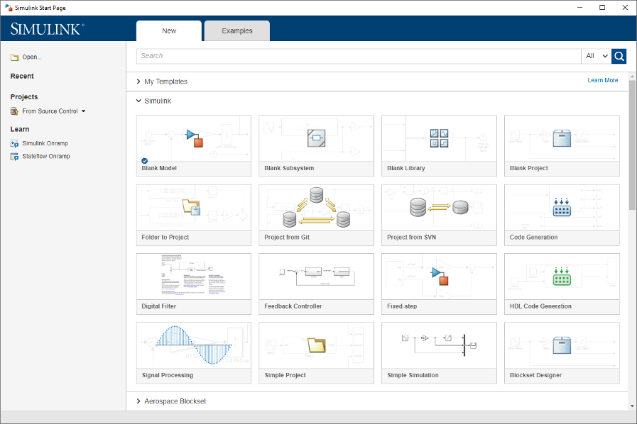
In this tutorial, we will introduce the basics of using Simulink to model and simulate a system.Simulink is supported on Unix, Macintosh, and Windows environments, and it is included in the student version of MATLAB for personal computers. Simulink is integrated with MATLAB and data can be easily transferred between the programs. Many elements of block diagrams are available (such as transfer functions, summing junctions, etc.), as well as virtual input devices (such as function generators) and output devices (such as oscilloscopes). In Simulink, systems are drawn on screen as block diagrams. Simulink is a graphical extension to MATLAB for the modeling and simulation of systems. Simulink Basics TutorialStarting Simulink Basic Elements Building a System Running Simulations


 0 kommentar(er)
